Self-Balancing
Furuta Pendulum

Brian Lui and Sam Hong,ECE 5725,December 2019

Introduction

The Rotary Inverted Pendulum, otherwise known as a Furuta pendulum, is a variation on a classic problem in the area of control system, the pendulum on a cart. Instead of being attached to a moving cart constrained to move linearly in only one dimension, the Furuta pendulum’s “cart” is a rotary object. The Furuta pendulum is an example of a nonlinear system, which also makes it more difficult to maintain upright. It is used to verify the performance of control algorithm techniques, of which can later be used to control more complicated systems, such as an aircraft flight. For an example of a Furuta pendulum, you can see a video of it here.


Our objectives were as follows:

  • Design the mechanical system, which composed of the pendulum, the arm, and the box
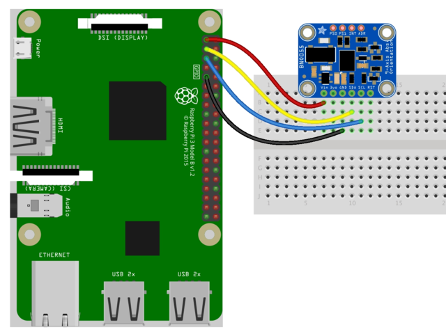
  • Read real-time data from the IMU
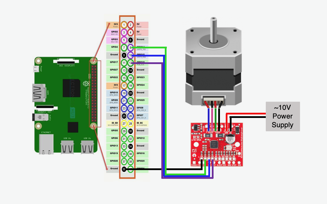
  • Design a controller to output the desired position of the stepper motor
  • Control the stepper motor with accuracy

You can watch a short demo video of our system below.


Design

Pendulum Assembly


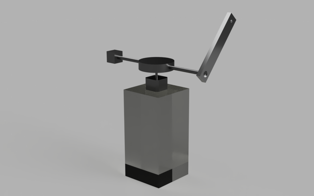
We decided to make our system primarily out of aluminum instead of 3D-printing all of the parts. The primary reason for this was that we wanted a very smooth rotation at the point of contact of the pendulum, allowing it to spin freely. The obvious answer for doing this was to use a ball bearing; rolling friction is lower than sliding friction. The system would also be more robust if made of metal, and it would be easier to attach with the shaft of the stepper motor. We purchased aluminum bars and rods from McMaster-Carr so that we could get to machining quickly. We used aluminum because it is easier to machine aluminum than it is to machine steel, and our application wasn’t subject to any high stresses that aluminum could not handle.

To the left is our initial CAD of the system. The entire pendulum assembly sits on top of a laser cut box so that the pendulum could be made longer. Thankfully, this ended up not being an issue, and you can see more photos of the machined parts below!
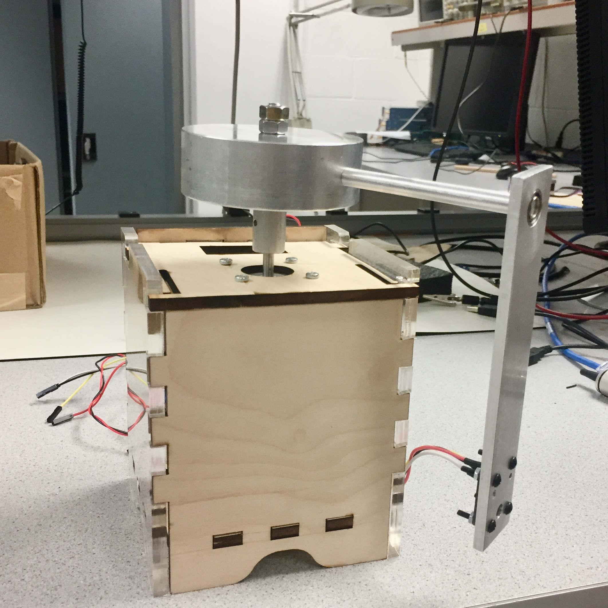
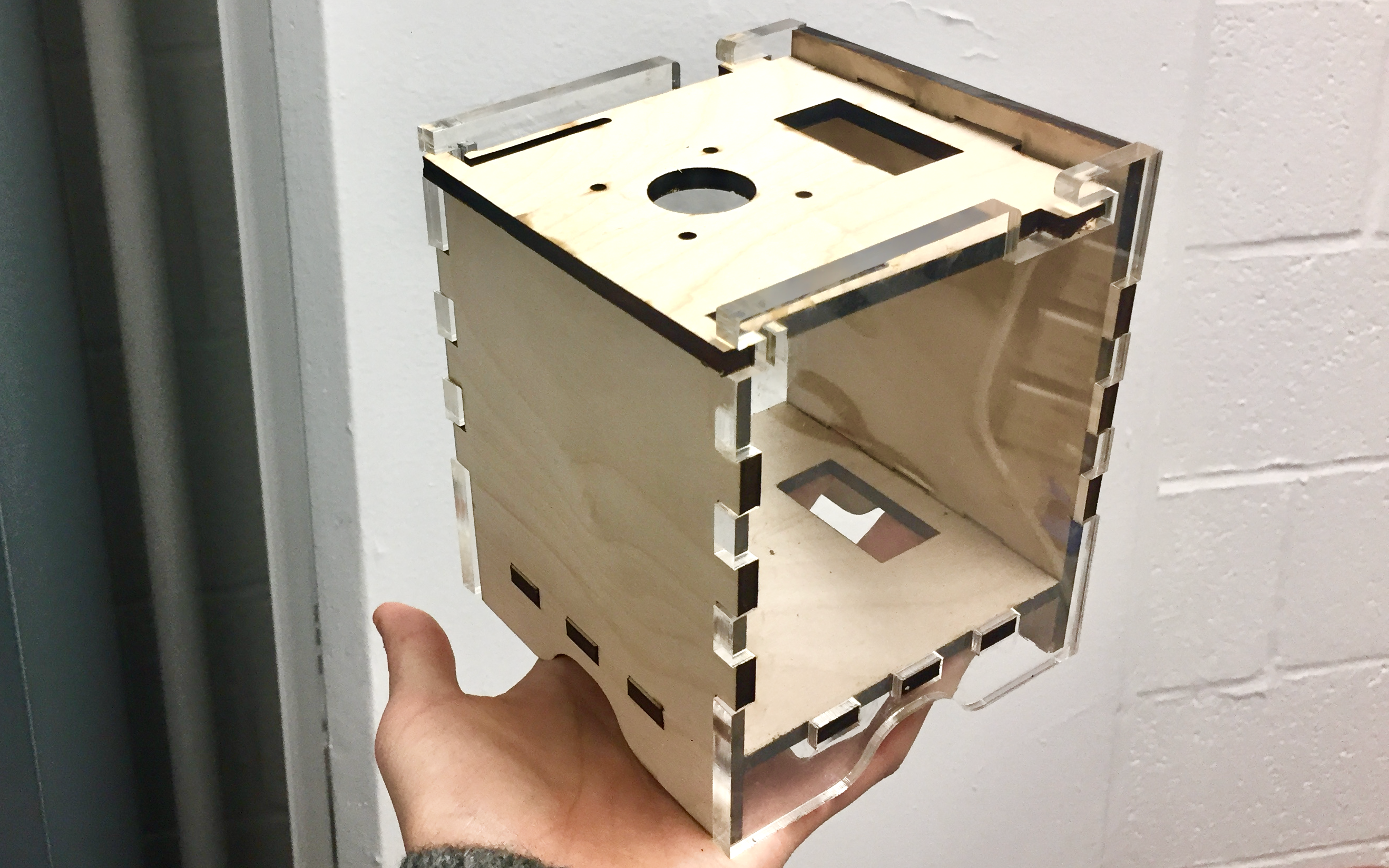
Housing

We decided to laser-cut a box to hold the breadboard with the motor driver and hide the excess wires. We originally wanted the box to be completely made of wood, but we ended up using clear acrylic for the sides, which ended up looking really cool.

Originally, we planned on having the motor sit on top of the box to provide enough height for the pendulum to swing around, but the vibrations from the stepper motor required us to have the motor clamped or fixed in some way. We later cut out holes on the top of the box so that we could screw on the motor from the inside of the box.


Controls

The pendulum, if undisturbed, would hang vertically downward because of the force of gravity. Therefore to get the pendulum to pointing vertically upward, we would need to apply a control input through controlling the motor to swing the pendulum up. This analysis was done using MATLAB, but it could have also been done using the SymPy and control libraries on Python.


Dynamics of Furuta Pendulum

We began by first deriving the dynamics of the system. We found a great paper online (Benjamin Seth Cazzolato and Zebb Prime 2011, “On the Dynamics of the Furuta Pendulum”). The paper made a few assumptions to the dynamics that wasn’t acceptable for our system and we wanted to understand the system better, so we decided to derive it ourselves. We decided to use the Lagrangian approach towards finding the dynamics, which involves finding the position and velocity of the pendulum. We assumed there was no damping in the system, and the only force acting on the system is gravity.

We then linearized our system about our desired equilibrium point, corresponding to theta = 0. This linearized form is only accurate near the equilibrium points; if the pendulum bar deviated too much away from the upright position, the dynamics would be very inaccurate in describing the motion.


Controls of the System

Once the dynamics of the furuta pendulum was derived, we could begin controlling it. We began by first looking at the root locus of the Furuta pendulum without any control. We could see that the system was unstable because there was a pole in the right half plane of the root locus. This was as expected: the pendulum without any control was not going to be stable. We also compared this root locus with that of other papers on the Furuta pendulum to act as another check that our derivation of the dynamics was correct. We also threw in a time delay to make the system more realistic: this was done by adding a Padé approximation to the feedback loop of the system. Using MATLAB’s sisotool (one of MATLAB’s many god-tier functions), we could look at how the properties of the system changed as we adjusted the controller. In order to get the root locus to be stable, we had to add a pole to the right of the rightmost zero: this would . Because we had decided to implement the system as a PID controller in the python code, the zero would occur at s = 0. Afterward, we added two zeros in the left hand plane to pull the right hand side poles left as the gain on the system increases. We picked the two zeros with two constraints in mind: we tried to minimize the overshoot because our refresh rate of our system was not very high, and we also tried to minimize the gain required because there were limitations on our system on the speed and torque that our motor could provide.


Hardware

IMU

An IMU, or inertial measurement unit, was needed because we have to know the position of the pendulum at all times. The reason we decided to use an IMU over a rotary encoder was because it was readily available, which is a choice that we elaborate more on in the ‘Results’ section.

Initially, we tried using Sparkfun MPU6050, a 6 degree of freedom IMU (3-axis accelerometer, 3-axis gyroscope). However, while using the sensor for a few weeks, we quickly realized that without an external filter, its accuracy would decrease over time. This would be a big problem in a controls-related project, as it would be difficult to maintain the pendulum upright if we can’t read proper angular position data.

Thankfully, we ended up getting our hands on the Adafruit BNO055, which is a 9 degree of freedom (3-axis accelerometer, 3-axis gyroscope, 3-axis magnetometer) sensor that has its own CircuitPython library. This makes the IMU much easier for us to use, as we don’t have to read from defined registers but rather call existing functions from the library. Additionally, the IMU implements its own sensor fusion algorithms, which made our life much more simpler. However, we did have to account for the fact that it has a slow sampling rate (100 Hz).


Stepper Motor + Motor Driver

Because we have to know the position of the motor at all times, we were deciding between using a DC motor with an encoder or a stepper motor. Although a DC motor performs better than a stepper motor in terms of torque, it is more expensive; also, we already had a stepper motor and a driver (Sparkfun Big Easy Driver), so we ultimately ended up using those components. We also talk more about this choice in the ‘Results’ section.

The motor that we chose to use has 400 steps per revolution, which means that each step angle is 0.9 degrees. Although this provided decent precision for us, we encountered a lot of vibrations as the shaft was rotating, so we did also use microstepping.


Software

Multithreading

As mentioned in the ‘Hardware’ section, our sensor outputs data at 100 Hz, or every 10 ms -- this is too slow for us. Doing everything (reading sensor output, feeding into our controller, controlling our motor properly) serially would take way too long, and we wanted to be able to continuously read sensor data regardless of what other tasks we would be doing.

While deciding between threading and multiprocessing, we took into account that we would have to continuously read sensor data and analyze it, so we wanted a module that would allow various functions to share objects within the same memory space. Because only one thread writes to a global list that stores sensor data and we do not have multiple threads writing to the same memory concurrently, we did not have to worry about using locks.

Because the controller functions at a much higher speed than the speed of the IMU, we needed to ensure that the controller only takes in new input. To do so, we made the controller check if the IMU had already taken in a new input. Additionally, we had to make sure that when there is a new output from the controller, the motor abandons whatever it was doing beforehand as to make sure to minimize delays.


Challenges

Stepper Motor

We faced many challenges with the stepper motor. One issue we faced was that we didn’t realize that the motor driver was not current limiting because the potentiometer was broken, which meant that the motor was becoming extremely hot and damaged. Toward the third week of this project, the motor just stopped working, so we had to search around for another one. We were able to use a friend’s stepper motor and driver, which saved us the trouble of paying high shipping fees to get one quickly.

We were very hesitant from the beginning about using a stepper motor, but we believed it could work because if we used microstepping with a very short delay time, we could achieve a decent amount of speed and precision. However, it wasn’t until when we implemented our controller that we realized that the system just could not work with a stepper motor. A stepper motor is usually chosen for its precision, not for its torque. The motor we were using just did not have enough power to maintain the pendulum upright.

Additionally, balancing an inverted pendulum requires great precision. Therefore, we wanted to characterize our motor, but after testing different stepping mode and delay time combinations, we learned that a stepper motor’s valid range of speed at different modes is nearly impossible to predict. Although we tried our best and implemented a look-up table in our code, we believe that our characterization was inconclusive.


Broken Components

As mentioned briefly above, we ran into some issues with broken parts, which halted our progress significantly. Another issue we had was that we initially 3D printed a shaft coupling. However, after a few days of use, we realized that plastic cannot hold metal very well, and we experienced a lot of slipping with the pendulum system secured onto the shaft of the motor. We ended up machining a proper shaft coupling out of metal. Had we machined it properly the first time, we wouldn’t have wasted a lot of time.


Conclusion

We accomplished a lot of tasks for this project. On the hardware and mechanical side, we were able to read accurate angle and angular rate readings for the pendulum and validate those readings through testing. We also, to the best of our abilities, characterized the stepper motor, machined the pendulum assembly, and designed housing to store all of our electrical components. On the software side, we were able to deal with the slow data output rate of the IMU by using multithreading and having that process continuously run in the background. Finally, on the controls side, we modeled our system on Matlab and designed a PID controller that gave us the proper output.

However, our major issue came with the stepper motor, which just did not provide enough torque for us. Additionally, choosing an IMU over an encoder was a big problem, as the IMU samples too slowly and cannot give accurate real-time information of the pendulum. The extra wires coming from the IMU ended up becoming an inconvenience as well and sometimes provided external force that we couldn't account for.

Overall, we definitely learned a lot throughout the entire process, from choosing the right hardware to writing clean and efficient code. We enjoyed the late nights and definitely appreciated a lot of technical advice from the TAs and Prof. Skovira.

tl;dr: we did a lot of good things, but all of those good things couldn’t overcome the fact that we didn’t use a DC motor.


Appendix

Acknowledgements

We thank Professor Skovira and ECE 5725 teaching assistants, all of whom provided guidance and encouragement when we ran into problems. Also, we were able to save a lot of money because Professor Skovira generously lent us the IMU, and we were also lent the motor driver and stepper motor from friends.

Code

The complete Python scripts, along with the derivations & controller designing scripts in Matlab that Brian spent a lot of time on, can be found on Github.


Work Contribution

Sam (sh974)

Hardware, Software, Website

Brian (bl569)

Mechanical Design, Controls, Software